RouterOS + tr069 staging process
- Install RouterOS in a virtual machine and connect it to CONTROL
- IPsec Configuration
- Setting up TR-069 client on mikrotik hAP ac2
Install RouterOS in a virtual machine and connect it to CONTROL
Overview
This guide walks you through installing RouterOS in a VirtualBox virtual machine and connecting it to CONTROL using the TR-069 protocol.
Prerequisites
- VirtualBox installed on your system
- Internet connection to download RouterOS files
- Basic familiarity with virtual machine management
Step 1: Download RouterOS
Visit the MikroTik download page and download the following files:
- RouterOS 6.48.6 Long-term x86 ISO image
- Extra packages (contains the TR-069 package)

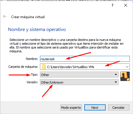
Step 2: Create the Virtual Machine
Configure VM Settings
- Open VirtualBox and create a new virtual machine
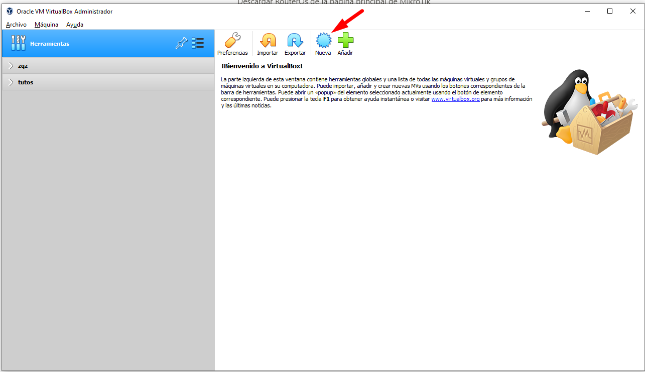
- Enter the required information as shown below
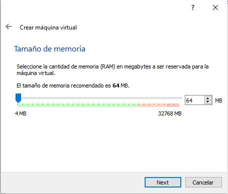
- Allocate RAM memory (64 MB is sufficient for RouterOS)
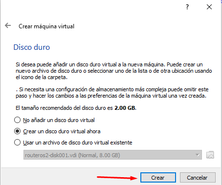
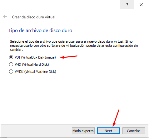
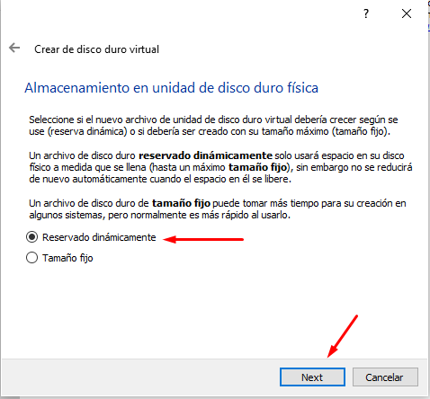
- Create a virtual hard disk with the following settings:

Configure Network Adapters
- After the VM is created, add an additional network adapter in the VM settings

- The network configuration should look like this:

Step 3: Install RouterOS
Boot and Installation
- Start the virtual machine

- Select the RouterOS ISO image and boot the VM

- When the package selection screen appears, press A to select all packages


- Press I to start the installation and confirm when prompted

- After installation completes, unmount the ISO image to prevent the installation wizard from restarting

Step 4: Initial Configuration
Login to RouterOS
- Once the login screen appears, use the default credentials:
-
Username:
admin - Password: (leave blank)
-
Username:

Assign IP Address
- Add an IP address to enable remote access. For this example, we'll use
192.168.1.50:
ip address add address=192.168.1.50/24 interface=ether1

- Verify the IP address was added correctly:
ip address print

Access Web Interface
- Open a web browser and navigate to the RouterOS web interface using the IP address you configured:
http://192.168.1.50/webfig/

- Click on WebFig to access the full configuration interface

Step 5: Install TR-069 Package

- Extract the downloaded Extra packages archive and locate the TR-069 package file


- Reboot the router to complete the package installation

- After reboot, verify that TR-069 is enabled in the system

Step 6: Obtain RouterOS License
RouterOS displays a warning message indicating you have 24 hours to use the software without a license. You must register to obtain a free demo license.
Save Software ID
- Note the Software ID displayed in the license warning message

Generate License Key
-
Register for a MikroTik account at the registration page
-
After logging in, navigate to MAKE A DEMO KEY, enter your Software ID, and generate the license


Activate License
- Connect to RouterOS via SSH

- Paste the license key in the terminal and reboot to complete activation

- After reboot, a confirmation message indicates the license was successfully activated
[
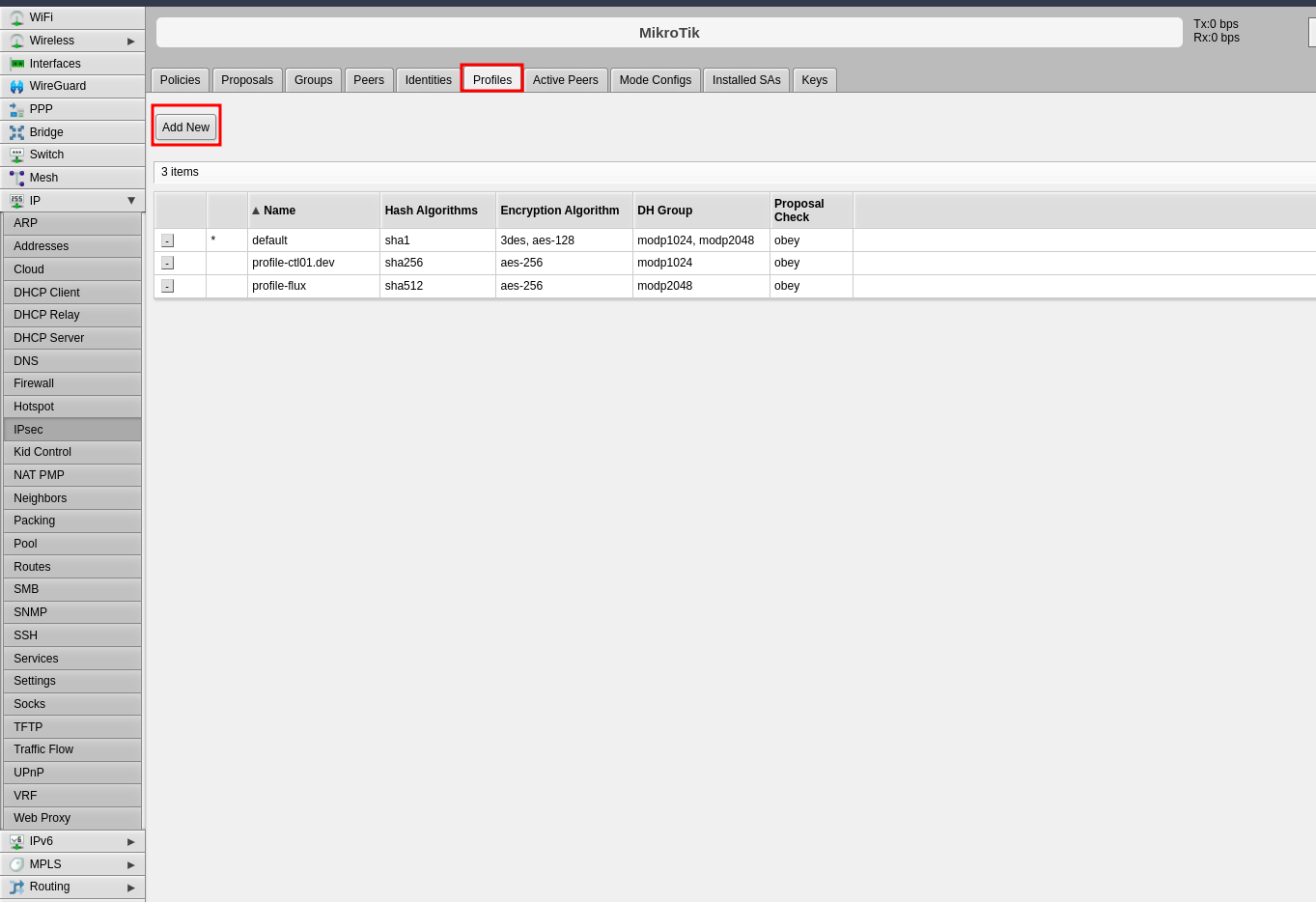
Step 1: Configure Profiles (Phase 1)
The profile defines Phase 1 parameters for the IPsec connection.
- Click the Profiles tab in the center panel
- Click Add New to create a new profile
-
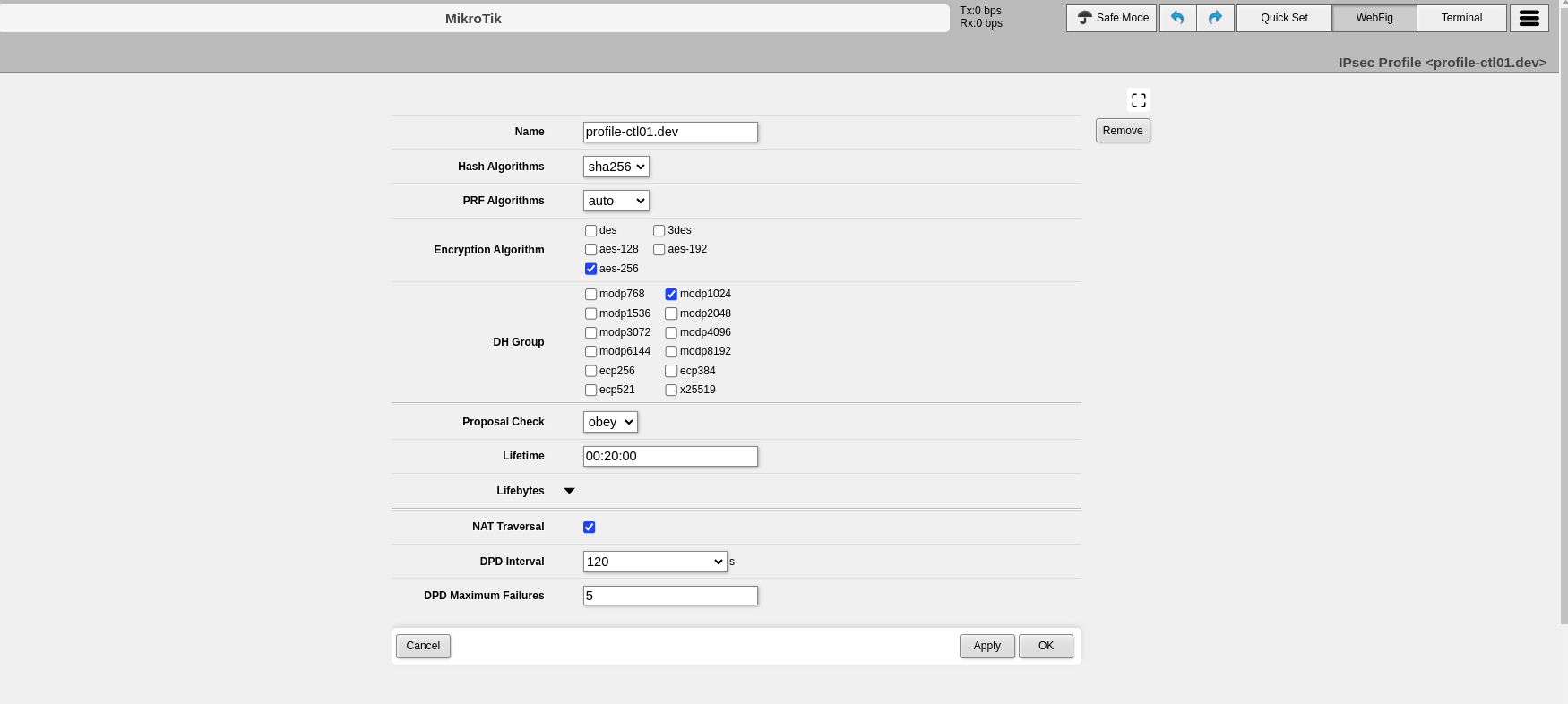
Configure the following Phase 1 parameters:
- Name: Enter a descriptive name to identify the profile (e.g., "profile-to-ctl01.dev")
- Hash Algorithms: Select a hash algorithm that matches the configuration on the remote endpoint
- Encryption Algorithm: Choose an encryption algorithm that matches the remote endpoint configuration
- Lifetime: Leave the default value (measured in seconds)
- NAT Traversal: Enable this option if the router is behind NAT
- DPD Interval: Leave the default value for Dead Peer Detection and note this number
- DPD Maximum Failures: Leave the default value
-
Click Apply, then click OK
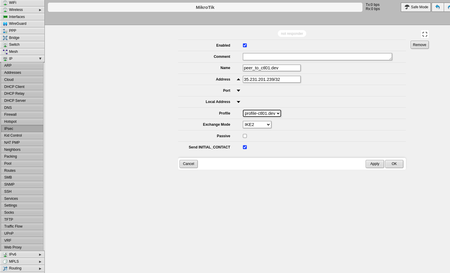
Step 2: Configure Peers
The peer configuration defines the remote VPN endpoint.
- Click the Peers tab
- Click Add New
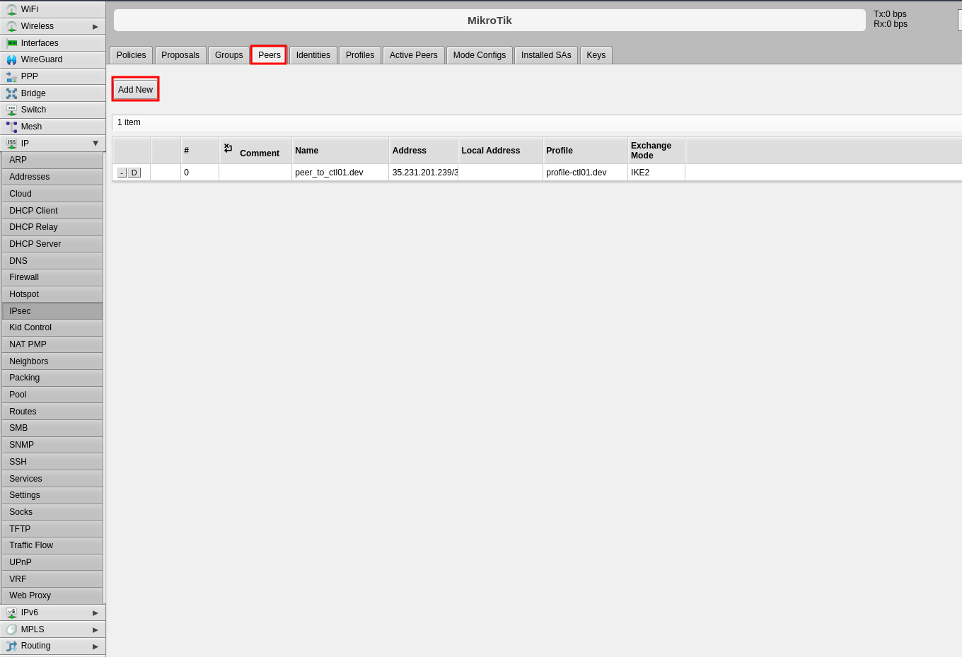
-
Configure the following fields:
- Name: Enter a name to identify the remote peer
- Address: Enter the remote public IP address (e.g., 35.35.35.22/32)
- Profile: Select the profile created in Step 1
- Exchange Mode: Select the exchange mode (IKE2 is recommended)
-
Click Apply, then click OK
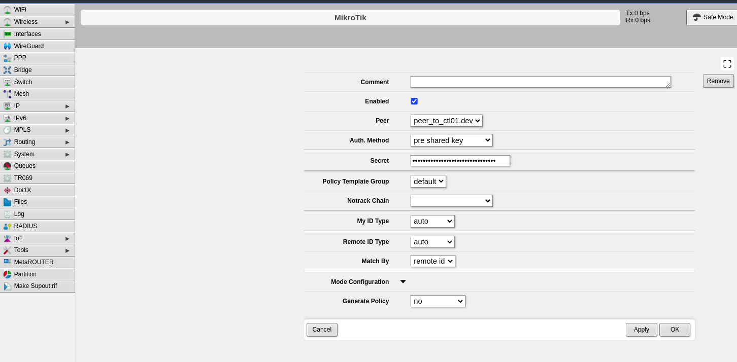
Step 3: Configure Identities
The identities configuration defines authentication credentials.
- Click the Identities tab
- Click Add New
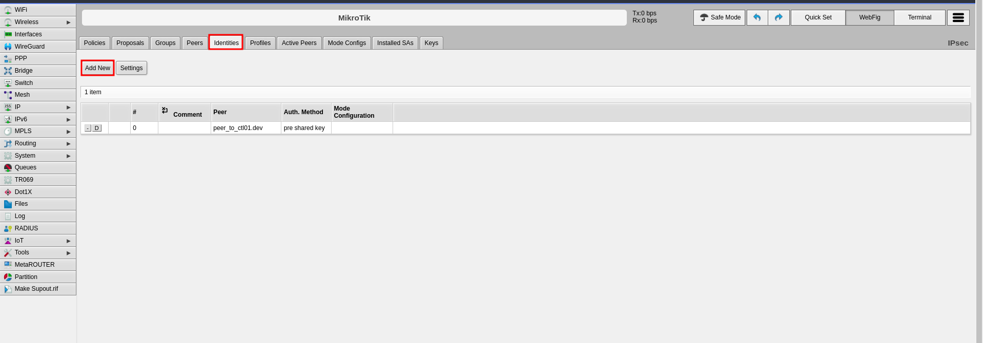
-
Configure the following fields:
- Peer: Select the peer configured in Step 2
- Auth. Method: Select "pre shared key"
- Secret: Enter the pre-shared key that will be configured on both endpoints
-
Click Apply, then click OK
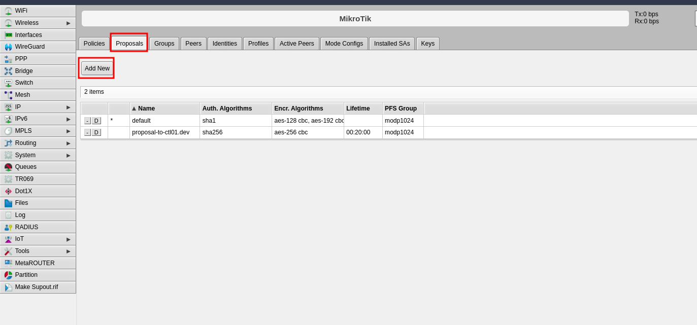
Step 4: Configure Proposals (Phase 2)
The proposal defines Phase 2 parameters for the IPsec connection.
- Click the Proposals tab
- Click Add New
-
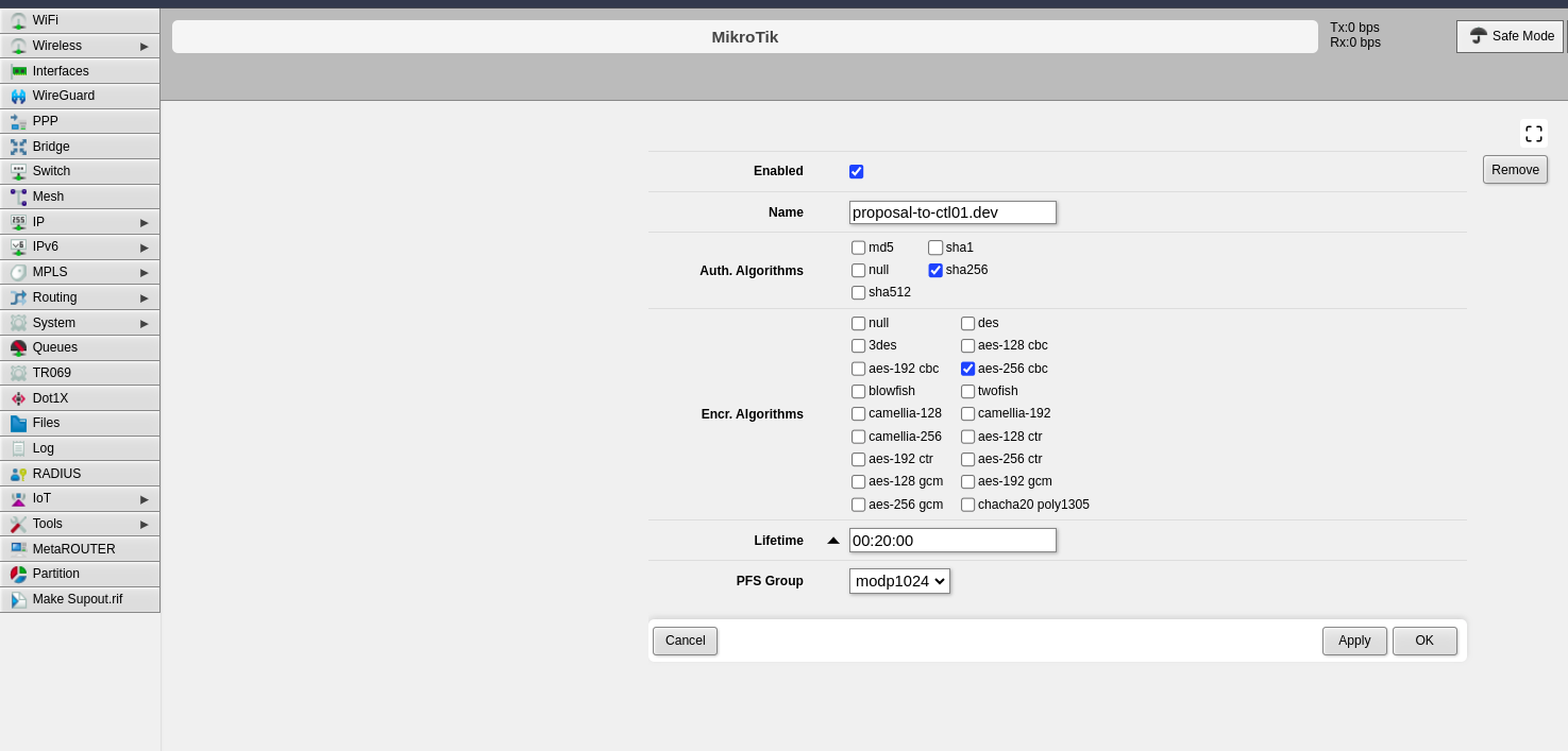
Configure the following Phase 2 parameters:
- Name: Enter a name to identify this proposal
- Auth. Algorithms: Select the authentication algorithm to be used on both endpoints
- Encr. Algorithms: Select the encryption algorithm to be used on both endpoints
- Lifetime: Set the lifetime for Phase 2
- PFS Group: Select the Diffie-Hellman group for Perfect Forward Secrecy (PFS). This determines the session key generation during key exchange
-
Click Apply, then click OK
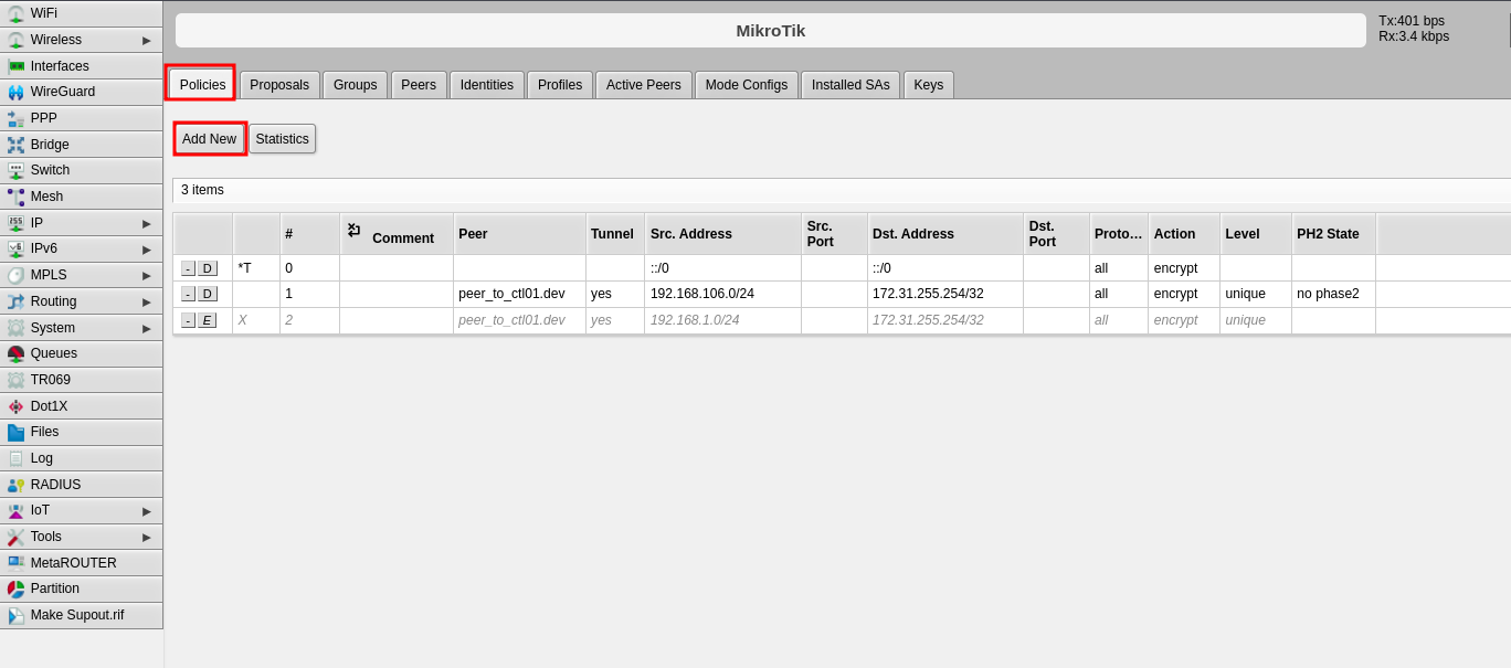
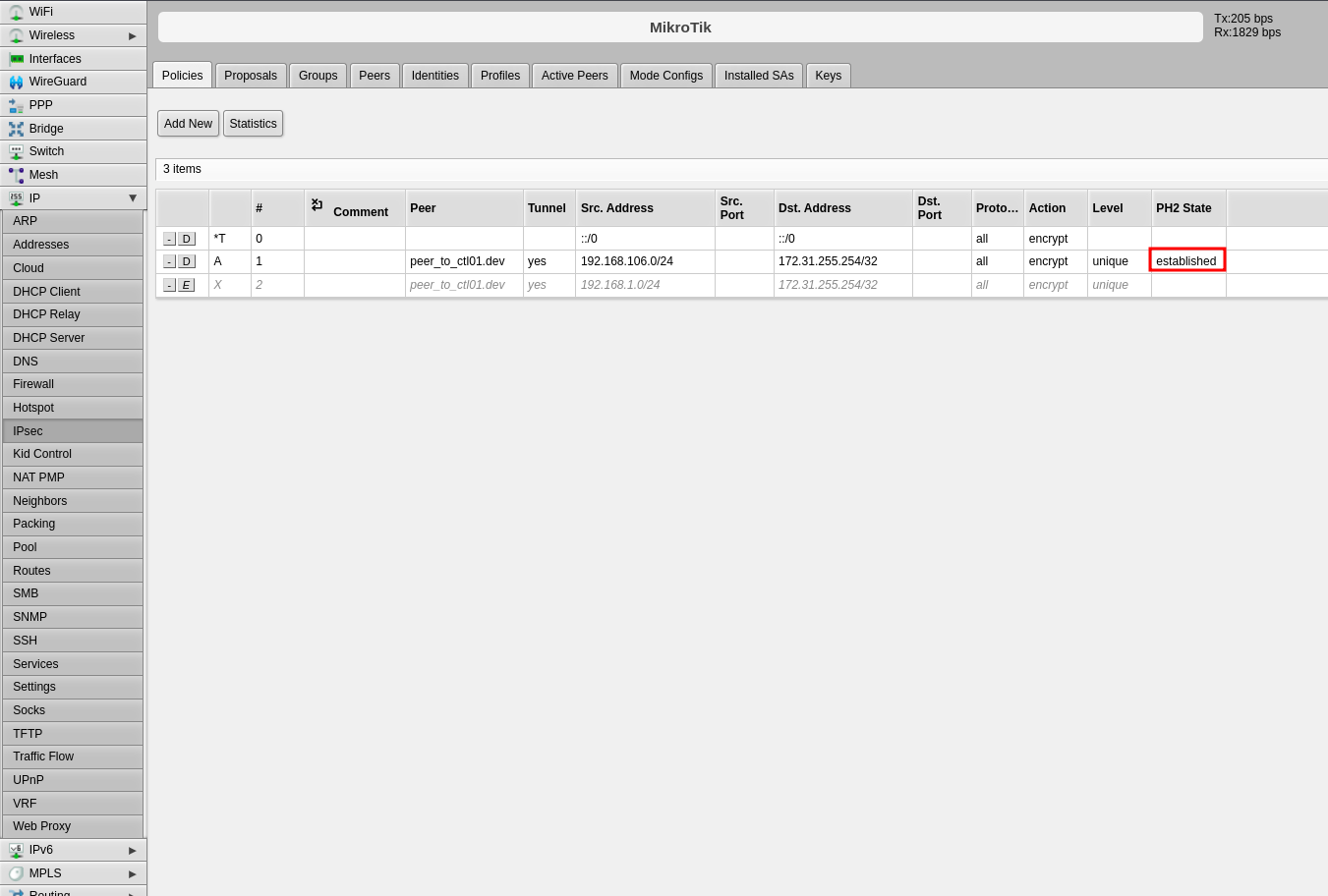
Step 5: Configure Policies
The policy defines which traffic should pass through the VPN tunnel.
- Click the Policies tab
- Click Add New
-
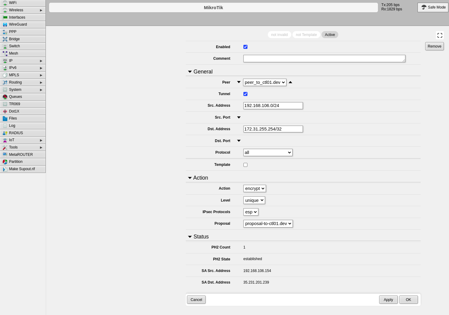
Configure the following fields:
- Peer: Select the peer configured in Step 2
- Tunnel: Enable this option to establish the tunnel between both sites
- Src. Address: Enter the local IP address or network that will pass through the tunnel
- Dst. Address: Enter the remote IP address or network that will be received from the other end
- Level: Select "unique"
- Proposal: Select the proposal created in Step 4
-
Click Apply, then click OK
Part 2: CONTROL Configuration
Initial Navigation
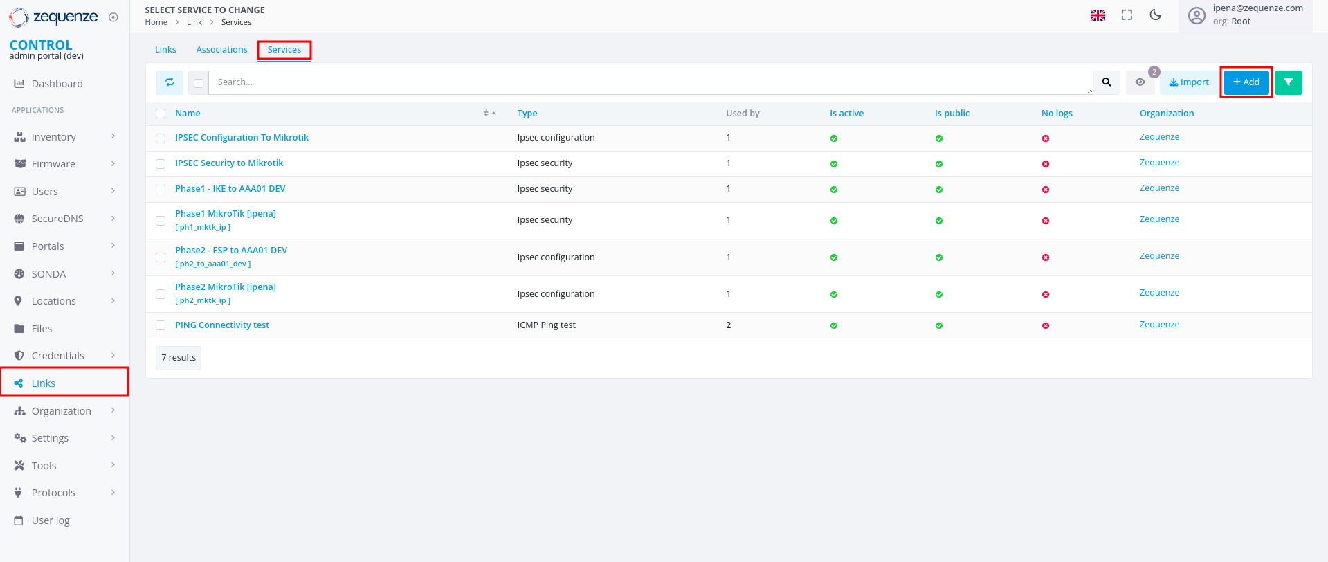
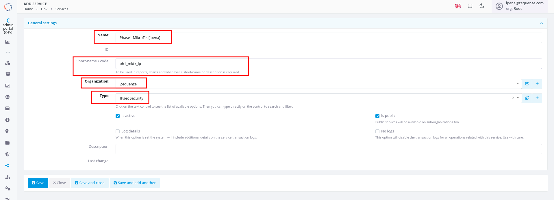
Step 1: Create IPsec Security Service (Phase 1)
-
Configure the basic information:
- Name: Enter a name to identify Phase 1
- Short-name/code: Enter a short identifier for quick reference
- Organization: Select the organization that will use this connection
- Type: Select "IPsec Security"
-
Click Save at the bottom
-
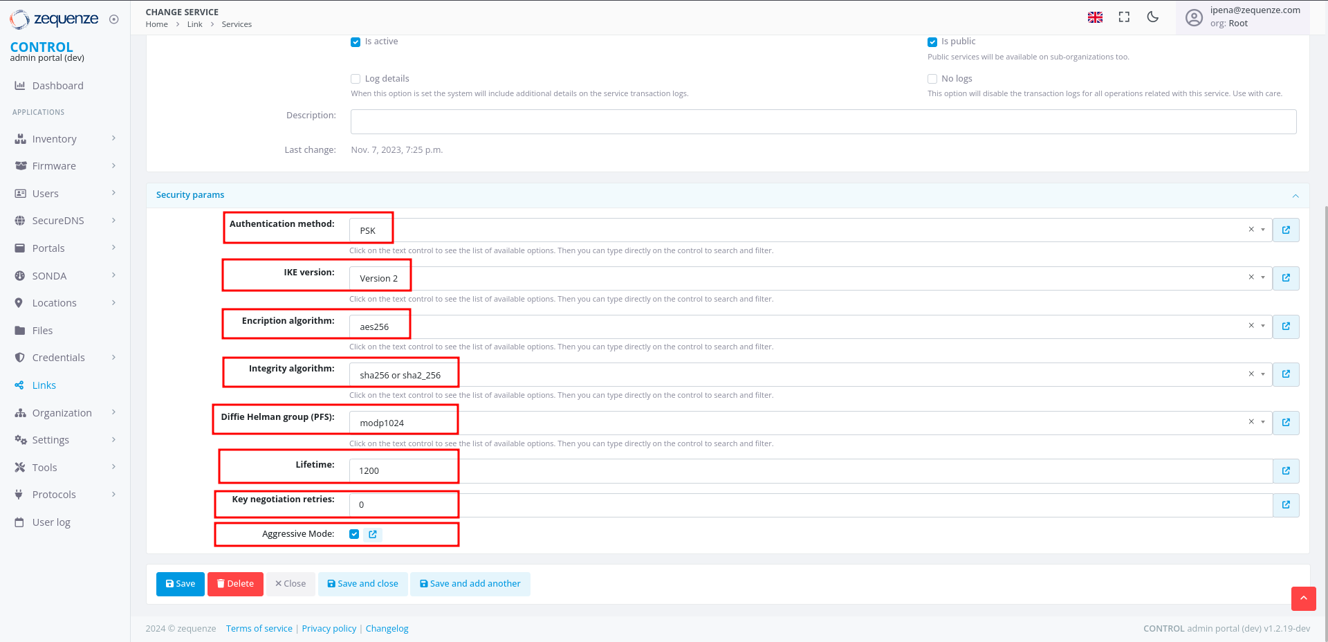
Configure the Phase 1 parameters to match your RouterOS configuration:
- Authentication method: Select "PSK"
- IKE version: Select "Version 2"
- Encryption algorithm: Enter "aes256"
- Integrity algorithm: Enter "sha256" or "sha2_256"
- Diffie Hellman group (PFS): Enter "modp1024"
- Lifetime: Enter 1200 (equivalent to 20 minutes)
- Key negotiation retries: Enter "0"
- Aggressive Mode: Enable this option
-
Click Save and close at the bottom
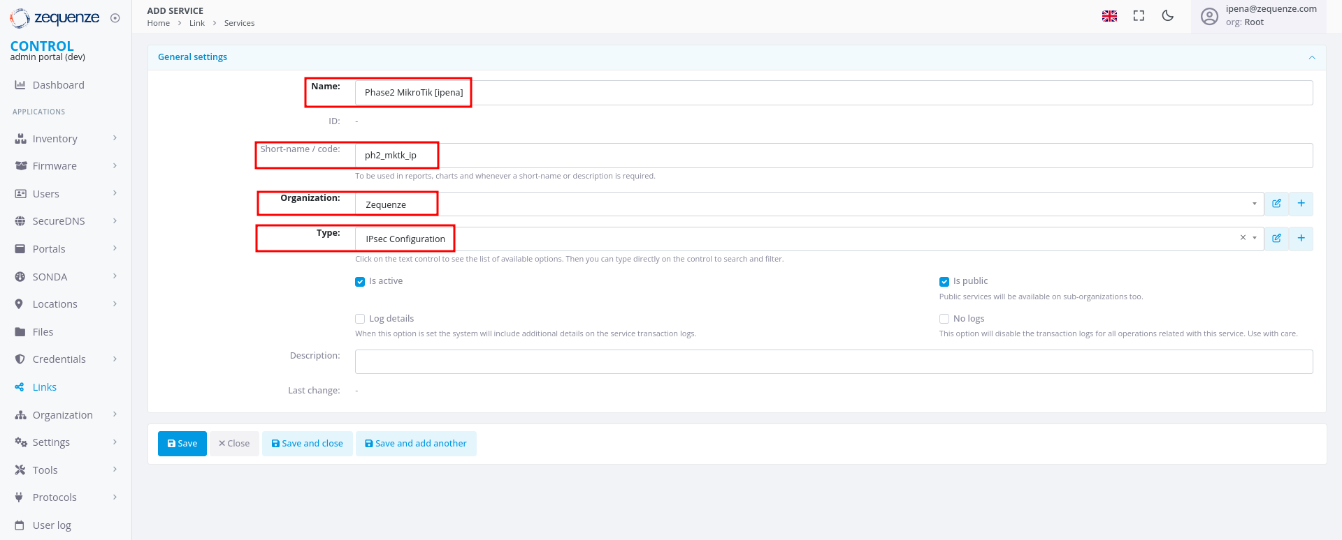
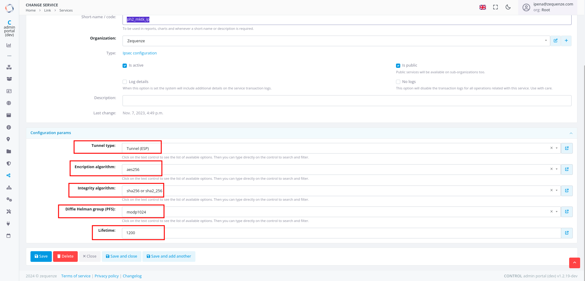
Step 2: Create IPsec Configuration Service (Phase 2)
-
In the Services tab, click +Add again to create another service
-
Configure the basic information:
- Name: Enter a name to identify Phase 2
- Short-name/code: Enter a short identifier for quick reference
- Organization: Select the organization that will use this connection
- Type: Select "IPsec Configuration"
-
Configure the Phase 2 parameters to match your RouterOS configuration:
- Tunnel type: Select "Tunnel (ESP)"
- Encryption algorithm: Enter "aes256"
- Integrity algorithm: Enter "sha256" or "sha2_256"
- Diffie Hellman group (PFS): Enter "modp1024"
- Lifetime: Enter 1200 (equivalent to 20 minutes)
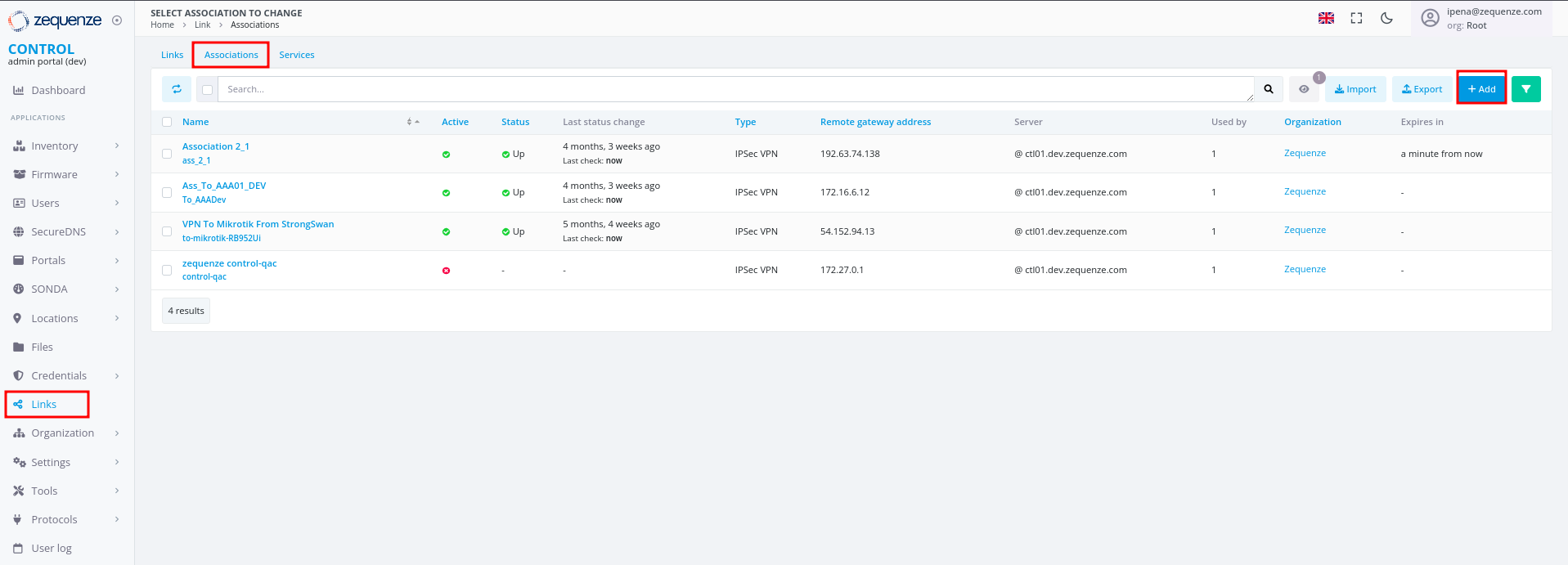
Step 3: Create Association
- In the Links section, select the Association tab
- Click the +Add button
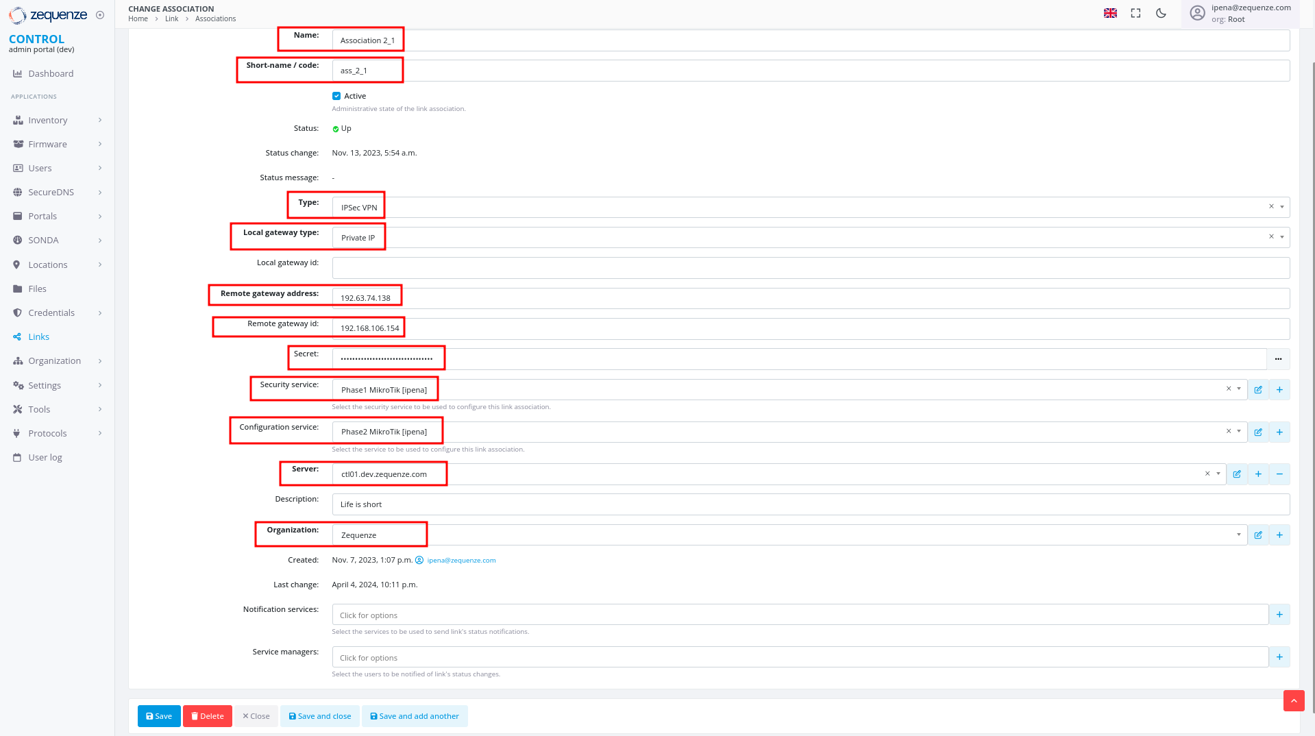
-
Configure the following fields:
- Name: Enter a name to identify this association
- Short-name / code: Enter a short identifier for quick reference
- Type: Leave "IPSec VPN" selected
- Local gateway type: Leave "Private IP" selected
- Remote gateway address: Enter the remote public IP address you are connecting to
- Remote gateway id: Enter the WAN interface IP of the RouterOS device
- Secret: Enter the pre-shared key (must match the secret configured in RouterOS)
- Security service: Select the IPsec Security service created in Step 1
- Configuration service: Select the IPsec Configuration service created in Step 2
- Server: Select the internal server to use
- Organization: Select the organization that will use this connection
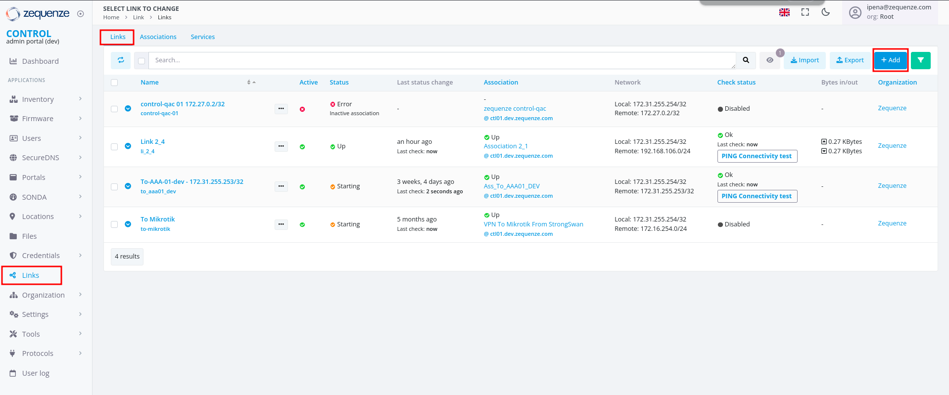
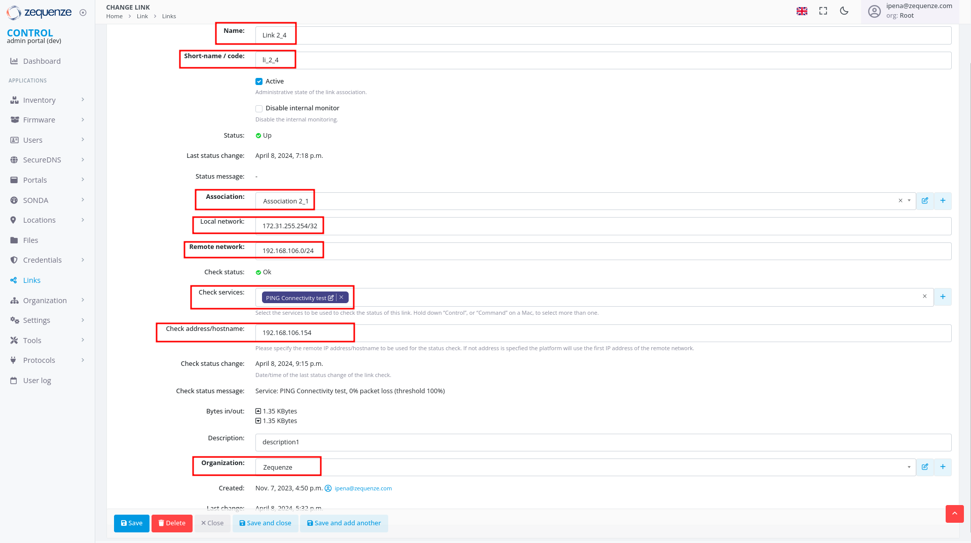
Step 4: Create Link
- In the Links section, ensure you are on the Links tab
- Click the +Add button
-
Configure the following fields:
- Name: Enter a name to identify this link
- Short-name / code: Enter a short identifier
- Active: Enable this option to activate the link
- Association: Select the association created in Step 3
- Local network: Enter the local Zequenze IP address
- For CONTROL: typically
172.31.255.254/32 - For GATE: typically
172.31.255.253/32 - (Verify the correct IP internally before configuring)
- For CONTROL: typically
- Remote network: Enter the remote network or IP address that will pass through the tunnel to Zequenze
- Check services: Select "PING Connectivity test" to validate tunnel communication
- Check address/hostname: Enter a remote IP address that is always active for connectivity testing (typically the remote gateway, e.g., 192.168.106.154)
- Organization: Select the organization that will use this VPN connectivity
Verification and Summary
RouterOS Connection Status
Once the configuration is complete, you should see the connection established in RouterOS as shown below:
CONTROL Connection Status
The Link within CONTROL should appear as follows when successfully established:
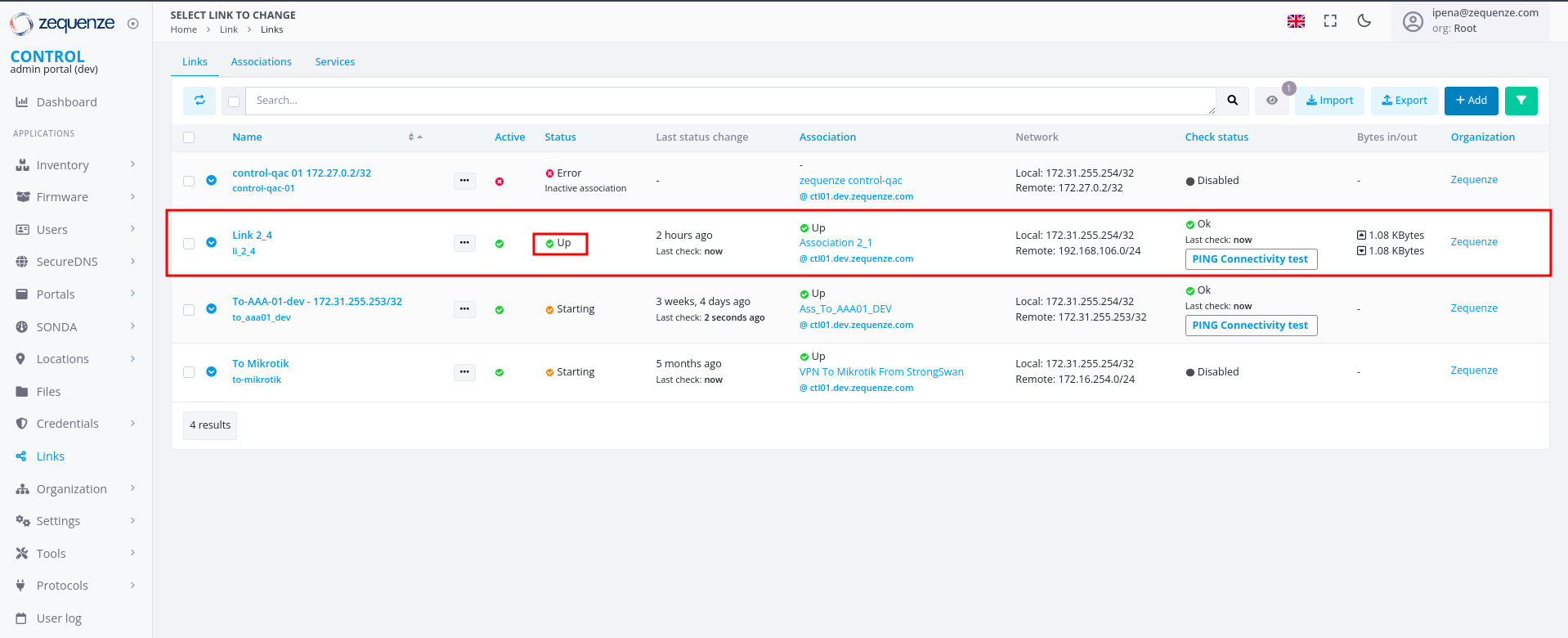
This completes the IPsec VPN tunnel configuration between RouterOS and CONTROL. The tunnel should now be active and passing traffic between the configured networks.
Setting up TR-069 client on mikrotik hAP ac2
Prerequisites
Before configuring the TR-069 client, ensure your MikroTik hAP ac2 device has an active internet connection.
Required Configuration Parameters
You will need the following credentials and settings to configure the TR-069 client in CONTROL:
- ACS URL: The endpoint URL where your device will report its status and receive management commands
- Username: Authentication username for the ACS URL
- Password: Authentication password for the ACS URL
Note: These credentials should be provided by your CONTROL administrator or obtained from your CONTROL portal settings.
Configuration Steps
Follow the video tutorial below for step-by-step instructions on configuring the TR-069 client on your MikroTik hAP ac2:
Additional Information
The TR-069 protocol enables remote management and monitoring of your MikroTik device through the CONTROL platform. Once configured, your device will automatically establish communication with the ACS server and appear in your CONTROL dashboard.